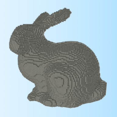
Today I want to write about what is probably the single most common question that gets asked regarding greedy meshes. Specifically:
How can greedy meshes be texture mapped?
One naive solution might be to create a separate texture for each block type, and then do a separate pass for each of these textures. However, this would require a number of state changes proportional to O(number of chunks * number of textures). In a world with hundreds of textures and thousands of chunks, this would be utterly unacceptable from a performance standpoint. Instead, a better solution is to use a technique called texture atlases.
Texture Atlases
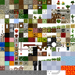
Now if you’ve ever modded Minecraft or looked inside a texture pack from before 1.5, the concept of a texture atlas should be pretty straightforward. Instead of creating many different textures, an atlas packs all of the different textures into a single gigantic texture:
Texture atlases can greatly reduce the number of draw calls and state changes, especially in a game like Minecraft, and so they are an obvious and necessary optimization. Where this becomes tricky is that in order to get texture atlases to work with greedy meshing, it is necessary to support wrapping within each subtexture of the texture atlas. In OpenGL, there are basically two ways to do this:
- Easy way: If your target platform supports array textures or some similar extension, then just use those, set the appropriate flags for wrapping and you are good to go!
- Hard way: If this isn’t an option, then you have to do wrapping and filtering manually.
Obviously the easy way is preferable if it is available. Unfortunately, this isn’t the case for many important platforms like WebGL or iOS, and so if you are writing for one of those platforms then you may have to resort to an unfortunately more complicated solution (which is the subject of this blog post).
Texture Coordinates
The first problem to solve is how to get the texture coordinates in the atlas. Assuming that all the voxel vertices are axis aligned and clamped to integer coordinates, this can be solved using just the position and normal of each quad. To get wrapping we can apply the fract() function to each of the coordinates:
vec2 tileUV = vec2(dot(normal.zxy, position),
                   dot(normal.yzx, position))
vec2 texCoord = tileOffset + tileSize * fract(tileUV)
Here the normal and position attributes represent the face normal and position of each vertex. tileOffset is the offset of the block’s texture in the atlas and tileSize is the size of a single texture in the atlas. For simplicity I am assuming that all tiles are square for the moment (which is the case in Minecraft anyway). Taking the fract() causes the texture coordinates (called texCoord here) to loop around.
Mipmapping Texture Atlases
Now the above technique works fine if the textures are filtered using GL_NEAREST or point filtering. However, this method quickly runs into problems when combined with mipmapping. There are basically two things that go wrong:
- Using an automatic mipmap generator like glGenerateMipmaps will cause blurring across texture atlas boundaries, creating visible texture seams at a distance.
- At the edge of a looped texture the LOD calculation will be off, and causing the GPU to use a much lower resolution mip level than it should.
At least the first of these problems is pretty easy to solve. The simple fix is that instead of generating a mipmap for all the tiles simultaneously, we generate a mipmap for each tile independently using periodic boundary conditions and pack the result into a texture map. This can be done efficiently using sinc interpolation and an FFT (for an example of how this works, check out this repository). Applying this to each tile in the texture atlas separately prevents any accidental smearing across boundaries. To compare, here are side-by-side pictures of standard full texture mipmapping compared to correct per-tile periodic mipmaps:
 Base Tilesheet
Left: Per-tile mipmap with wrapping. Right: Naive full texture mipmap.

Level 1


Level 2


Level 3


Level 4
If you click and zoom in on those mipmaps, it is pretty easy to see that the ones on the left side have fewer ringing artefacts and suffer bleeding across tiles, while the images on the right are smeared out a bit. Storing the higher mip levels is not strictly necessary, and in vanilla OpenGL we could use the GL_TEXTURE_MAX_LEVEL flag to avoid wasting this extra memory. Unfortunately on WebGL/OpenGL ES this option isn’t available and so a storing a mipmap for a texture atlas can cost up to twice as much memory as would be required otherwise.
The 4-Tap Trick
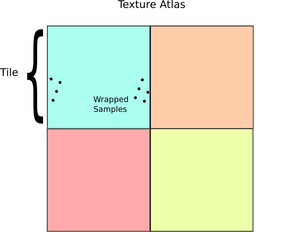
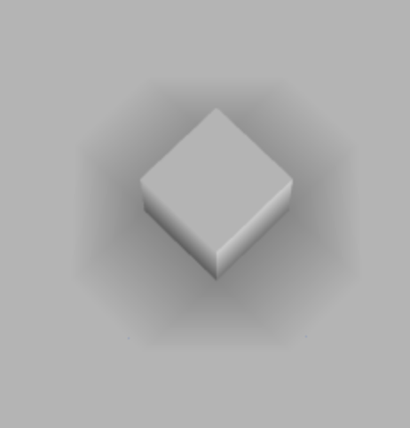
Getting LOD selection right requires a bit more creativity, but it is by no means insurmountable. To fix this problem, it is first necessary to understand how texture LODs are actually calculated. On a modern GPU, this is typically done by looking at the texture reads within a tiny region of pixels on the screen and then selecting a mip level based on the variance of these pixels. If the pixels all have very large variance, then it uses a higher level on the mip pyramid, while if they are close together it uses a lower level. In the case of our texture calculation, for most pixels this works well, however at the boundary of a tile things go catastrophically wrong when we take the fract():

Notice the grey bars between textures. In actual demo the precise shape of these structures is view dependent and flickers in a most irritating and disturbing manner. The underlying cause of this phenomenon is incorrect level of detail selection. Essentially what is happening is that the shader is reading texels in the following pattern near the edges:
The GPU basically sees this access pattern, and think: “Gosh! Those texels are pretty far apart, so I better use the top most mip level.” The result is that you will get the average color for the entire tile instead of a sample at the appropriate mip level. (Which is why the bands look grey in this case).
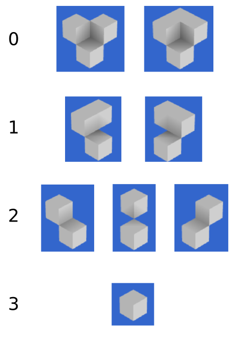
To get around this issue, we have to be a bit smarter about how we access our textures. A fairly direct way to do this is to pad the texture with an extra copy of itself along each axis, then sample the texture four times:
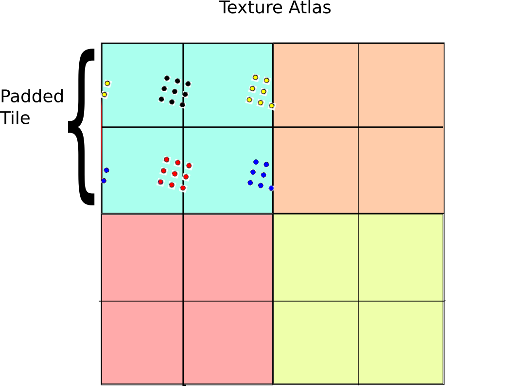
The basic idea behind this technique is a generalized form of the pigeon hole principle. If the size of the sample block is less than the size of the tile, then at least one of the four sample regions is completely contained inside the 2×2 tile grid. On the other hand, if the samples are spread apart so far that they wrap around in any configuration, then they must be larger than a tile and so selecting the highest mip level is the right thing to do anyway. As a result, there is always one set of samples that is drawn from the correct mip level.
Given that at least one of the four samples will be correct, the next question is how to select that sample? One simple solution is to just take a weighted average over the four samples based on the chessboard distance to the center of the tile. Here is how this idea works in psuedo GLSL:
vec4 fourTapSample(vec2 tileOffset, //Tile offset in the atlas
                  vec2 tileUV, //Tile coordinate (as above)
                  float tileSize, //Size of a tile in atlas
                  sampler2D atlas) {
  //Initialize accumulators
  vec4 color = vec4(0.0, 0.0, 0.0, 0.0);
  float totalWeight = 0.0;

  for(int dx=0; dx<2; ++dx)
  for(int dy=0; dy<2; ++dy) {
    //Compute coordinate in 2x2 tile patch
    vec2 tileCoord = 2.0 * fract(0.5 * (tileUV + vec2(dx,dy));

    //Weight sample based on distance to center
    float w = pow(1.0 - max(abs(tileCoord.x-1.0), abs(tileCoord.y-1.0)), 16.0);

    //Compute atlas coord
    vec2 atlasUV = tileOffset + tileSize * tileCoord;

    //Sample and accumulate
    color += w * texture2D(atlas, atlasUV);
    totalWeight += w;
  }

  //Return weighted color
  return color / totalWeight
}
And here are the results:

Demo
All this stuff sounds great on paper, but to really appreciate the benefits of mipmapping, you need to see it in action. To do this, I made the following demo:
http://mikolalysenko.github.io/voxel-mipmap-demo/
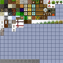
And here is a screenshot:
 Some things to try out in the demo are displaying the wireframes and changing the mip map filtering mode when zooming and zooming out. The controls for the demo are:
- Left click: Rotate
- Right click/shift click: Pan
- Middle click/scroll/alt click: Zoom
The code was written using browserify/beefy and all of the modules for this project are available on npm/github. You can also try modifying a simpler version of the above demo in your browser using requirebin:
http://requirebin.com/?gist=5958022
Conclusion
In conclusion, greedy meshing is a viable strategy for rendering Minecraft like worlds, even with texture mapping. One way to think about greedy meshing from this perspective is that it is a trade off between memory and vertex shader and fragment shader memory. Greedy meshing drastically reduces the number of vertices in a mesh that need to be processed by merging faces, but requires the extra complexity of the 4-tap trick to render. This results in lower vertex counts and vertex shader work, while doing 4x more texture reads and storing 4x more texture memory. As a result, the main performance benefits are most important when rendering very large terrains (where vertex memory is the main bottleneck). Of course all of this is moot if you are using a system that supports texture arrays anyway, since those completely remove all of the additional fragment shader costs associated with greedy meshing.
Another slight catch to the 4-tap algorithm is that it can be difficult to implement on top of an existing rendering engine (like three.js for example) since it requires modifying some fairly low level details regarding mipmap generation and texture access. In general, unless your rendering engine is designed with some awareness of texture atlases it will be difficult to take advantage of geometry reducing optimizations like greedy meshing and it may be necessary to use extra state changes or generate more polygons to render the same scene (resulting in lower performance).


